Rockwell Hardness Test
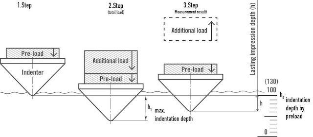
The Rockwell hardness test method consists of indenting the test material with a diamond cone or hardened steel ball indenter. The indenter is forced into the test material under a preliminary minor load FO usually I 0 kgf. When equilibrium has been reached, an indicating device, which follows the movements of the indenter and so responds to changes in depth of penetration of the indenter is set to a datum position. While the preliminary minor load is still applied an additional major load is applied with resulting increase in penetration . When equilibrium has again been reach, the additional major load is removed but the preliminary minor load is still maintained. Removal of the additional major load allows a partial recovery, so reducing the depth of penetration. The permanent increase in depth of penetration, resulting from the application and removal of the additional major load is used to calculate the Rockwell hardness number.
H R = E - e
FO = preliminary minor load in kgf
F1 = additional major load in kgf
F = total load in kgf
e = permanent increase in depth of penetration due to major load Fl measured in units of 0.002 mm
E = a constant depending on form of indenter: I 00 units for diamond indenter, 130 units for steel
ball indenter
HR = Rockwell hardness number
D = diameter of steel ball
 |