MACRO SECTION


MACRO SECTION

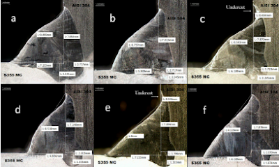
Object: To examine a cross section of a weld for internal defects and soundness.

Method:  A transverse section of the weld is cut out. The cross section is then visually inspected. The section is filed down from rough to smooth, then emery or wet/dry papered down to a surface finish of 600 grit. The surface is then etched in NITAL (5% - 10% nitric acid in alcohol), washed off, rinsed and dried. (Possibly a final clean with acetone and mount in Bakelite) The specimen is then inspected at up to 10-x magnification.

MACRO SECTION


Reporting Results:
  1. Material.
  2. Welding process.
  3. Specimen identification.
  4. Sentencing standard.
  5. Thickness.
  6. Geometric flaws - type, size and location.
  7. Internal flaws - type, size and location.
  8. Parent metal flaws - type, size and location.
  9. Accept or reject, to standard, for each flaw.   
Comparison of macro section and micro section:

                                                                       MACRO                                            MICRO

Magnification                                                  x 10                                                 x 1000

Finish                                                            600 grit                                    1 micron (high level polish)

Features/ defects                                     cracks, slag, LOF, etc.                        inter granular structure

Uses                                                   procedure/welder qualification              research/failure analysis
Popular posts from this blog

The Brinell Hardness Test

The Brinell Hardness Test The Brinell hardness test method consists of indenting the test material with a 10 mm diameter hardened steel or carbide ball subjected to a load of 3000 kg. For softer materials the load can be reduced to 1500 kg or 500 kg to avoid excessive indentation. The full load is normally applied for 10 to 15 seconds in the case of iron and steel and for at least 30 seconds in the case of other metals. The diameter of the indentation left in the test material is measured with a low powered microscope. The Brinell harness number is calculated by dividing the load applied by the surface area of the indentation. The diameter of the impression is the average of two readings at right angles and the use of a Brinell hardness number table can simplify the determination of the Brinell hardness. A well structured Brinell hardness number reveals the test conditions, and looks like this, "75 HB 10/500/30" which means that a Brinell Hardness of 75 was obtained us...

BEND TESTS

BEND TESTS Object:   To determine the soundness of weld metal, heat affected zone and weld zone.These tests may also be used to give some measure of the ductility of the weld zone. It is not usual to use transverse and longitudinal bend tests for the same application. Method:   All specimens to be removed and prepared without causing significant distortion or heating. The cap and root are ground flush. The specimen is bent by the movement of a former of prescribed diameter, the relevant side of the specimen to be placed in tension. Angle of bend and diameter of former should be as specified in the appropriate standard. Reporting Results: Thickness of specimen Direction of bend (root or face) Angle of bend Diameter of former Appearance of joint after bending e.g. type and location of flaws

MAGNETIC PARTICLE EXAMINATION (M.P.I.)

MAGNETIC PARTICLE EXAMINATION (M.P.I.) INTRODUCTION This method is used for detecting cracks and other discontinuities open to surface or sub surface in ferromagnetic materials. Fine magnetic particles are applied to the surface of a part which has been suitably magnetized. The particles are attracted to regions of magnetic non-uniformity associated with defects and discontinuities, thus producing indication which are observed visually. PRINCIPLE When a piece of metal is placed in a magnetic field and the lines of magnetic flux get intersected by a discontinuity such as a crack or slag inclusion in a casting, magnetic poles are induced on either side of the discontinuity. The discontinuity causes an abrupt change in the path of magnetic flux flowing through the casting normal to the discontinuity, resulting a local flux leakage field and interfering with the magnetic lines of force. This local flux disturbance can be detected by its affect upon magnetic particles that collect o...