RADIOGRAPHY TEST
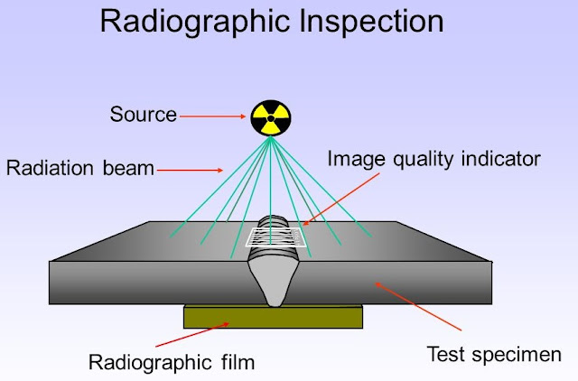
INTRODUCTION :Industrial radiography is a nondestructive test method that uses X-rays or Gamma rays to show the presence and certain characteristics of internal discontinuities in solid materials. The method is based on the ability of X-ray or Gamma-ray radiation to penetrate solids, to a degree that varies with such factors as wave length of the radiation, and type and thickness of the material part of the radiation penetrates the material and part is absorbed. The amount absorbed and the amount transmitted are a function of the thickness of the material.
Where a void or discontinuity exists, there is essentially less material to absorb the radiation. This creates a different in absorption, a difference that registers on photographic emulsions. The result is a shadow picture called a radiography
Radio-graphic Sources :
The common gamma ray radio-graphic sources :
Gamma Ray Radiography :Gamma rays are high energy electromagnetic waves of relatively short wavelength that are emitted during the radioactive decay of both naturally occurring and artificially produced unstable Isotopes. Many of the elements in the periodic table either have naturally occurring radioactive. However Radium and its salts become decompose at a constant rate giving out Gamma Rays which are of much shorter wavelength and more penetrating than x-rays.
The apparatus necessary for Gamma-Ray radiography is very simple. Cobalt-60 sources which are cylindrical with dimension of 3 x 3 to 6 mm and sealed in an appropriate container or capsule. Unlike x-rays, Gamma-Rays from its source are emitted in all directions. Therefore a no. of separate welded objects having cassette containing film fastened to the back of each object are disposed in a circle around the source placed in a central position. This way many welded objects can be radiographed simultaneously and overnight exposure may be taken without continuous supervision.
X-Ray Radiography Procedure:
X-ray produced in an X-ray tube where a (cathode) filament provides electrons which proceed towards the target (anode), strikes and suddenly stopped, a part of their kinetic energy is converted to energy of radiation or X-rays.
The portion of the casting where defects as suspected is exposed to X-rays emitted from the X-ray tube. A cassette containing X-ray film is placed behind and is in contact with metal, perpendicular to the rays.
Since most defects (such as blow holes, porosity, cracks, etc.) possess lesser density than the sound metal, they transmit X-rays better then the sound metal does; therefore the filmappears to be more dark where defects are in line of the X-ray.
INTRODUCTION :Industrial radiography is a nondestructive test method that uses X-rays or Gamma rays to show the presence and certain characteristics of internal discontinuities in solid materials. The method is based on the ability of X-ray or Gamma-ray radiation to penetrate solids, to a degree that varies with such factors as wave length of the radiation, and type and thickness of the material part of the radiation penetrates the material and part is absorbed. The amount absorbed and the amount transmitted are a function of the thickness of the material.
Where a void or discontinuity exists, there is essentially less material to absorb the radiation. This creates a different in absorption, a difference that registers on photographic emulsions. The result is a shadow picture called a radiography
Radio-graphic Sources :
The common gamma ray radio-graphic sources :
- Cobalt - 60
- Cesium - 137
- Iridium - 192
- Thulium - 170
The apparatus necessary for Gamma-Ray radiography is very simple. Cobalt-60 sources which are cylindrical with dimension of 3 x 3 to 6 mm and sealed in an appropriate container or capsule. Unlike x-rays, Gamma-Rays from its source are emitted in all directions. Therefore a no. of separate welded objects having cassette containing film fastened to the back of each object are disposed in a circle around the source placed in a central position. This way many welded objects can be radiographed simultaneously and overnight exposure may be taken without continuous supervision.
X-Ray Radiography Procedure:
X-ray produced in an X-ray tube where a (cathode) filament provides electrons which proceed towards the target (anode), strikes and suddenly stopped, a part of their kinetic energy is converted to energy of radiation or X-rays.
The portion of the casting where defects as suspected is exposed to X-rays emitted from the X-ray tube. A cassette containing X-ray film is placed behind and is in contact with metal, perpendicular to the rays.
Since most defects (such as blow holes, porosity, cracks, etc.) possess lesser density than the sound metal, they transmit X-rays better then the sound metal does; therefore the filmappears to be more dark where defects are in line of the X-ray.
